BA1b Brief
BA1b consists of 3 project briefs, which as Asset creation, Games Industry Role and Practice, and Introduction to Games Studies.
As 3D modelling is completely new to me, understanding the basic terminology is important.
A 3D model compromises of Vertices (X,Y and Z), Edges (lines that join at 2 vertices) and Faces.
A Polygon is as surface of a solid object that has at least 3 straight lines e.g. triangle, square, N-Gons)
N-Gons are polygons that are made up of 5 or more edges.
Materials consist of multiple textures which dictate how the model will react under light.
Textures are an image that represent how your model will look. The user chooses how many textures are used in a material.
The main textures I will be using are Albedo, normal, metallic and roughness maps.
Albedo Maps are the base colour input (also known as diffuse map), they have no directional light or shadow information, only variation of colour.
Normal Maps add surface detail as they are transferred onto the high poly mesh onto the low poly mesh through 'baking'.
Both Albedo and Normal maps are RGB.

http://vincent-gros.com/wp-content/uploads/2012/11/pillar03.jpg
Metallic Maps control how metal-like my surface will be and is always in grey scale.
Computer textures must follow the power of 2 sized pixel rule and are usually square - this way suits graphics hardware

http://www.marmoset.co/wp-content/uploads/materialref02.png
Examples and more information can be found on this website.
http://www.marmoset.co/toolbag/learn/pbr-practice
Other maps include:
- Emissive Maps - This map is in greyscale, can control parts of the material that will glow. White values allow maximum light, and black allows no light.

http://renderlights.com/online-help/lib/emissivity.jpg
- Ambient Occlusion - This map is also in greyscale. It is a rendering trick the shades areas of the map.
 http://www.independentdeveloper.com/images/ambient-occlusion.jpg
http://www.videocopilot.net/blog/wp-content/uploads/2012/07/ambient_occlusion.jpg
Realistic and hand-painted materials
Realistic materials are seen in games with a larger memory allocation, such as PC and console based games. No light information is in the albedo map, that is stored in the ambient occlusion map.
Hand-painted materials are seen in games with limited memory space such as mobile games, or those that are heavy in animation/game play. Light information is painted into the albedo map.
Hand-painted materials can still be seen in console/PC games, dependent on the style of the game; it can give a more stylized look.
Shaders are instructions applied to 3D models that lets the computer know how it's displayed.
http://3d.about.com/od/3d-101-The-Basics/a/Anatomy-Of-A-3d-Model.htm http://www.informit.com/articles/article.aspx?p=2162089&seqNum=2
Light types are directional, point, and spot lights.
- Directional light comes from a source infinitely far away, and is the ideal choice for mimicking sunlight.
- Point lights emit light equally in all directions, like a light bulb.
- Spot lights emit from a single point in a cone shape.
I had my first session using Maya, and over the couple of hours I created a basic lamp. I enjoyed playing around with the multiple options and exploring what I could create. The first image i created the lamp head using two primitives, but later tried making the head out of the same shape by extruding and adjusting it (as shown in the second image). I found this a lot hard and struggled getting the dome inside. Whilst using the connect option I messed up the polygons on the side as you can see in the side view image.


I then created one at home using Maya, using the knowledge from the session.


For a fresh start a I began creating another lamp from primitive polygons. I have gotten quicker and more confident with the basics in Maya and found this model easier


UV Mapping
The next part of the process is UV mapping the model. To start with I have been taught how to UV map a square, and created a dice. I am repeating this at home so I get to grips with the new options and have a good understanding so I can UV map more complex items soon.
U and V represent the same co-ordinates as X and Y in 2D space.
The layout I will be working in is a 0-1 space. If the UV is scaled out of this space it will be repeated on the model respectively.
The process of UV mapping is basically unwrapping the 3D object onto a 2D surface. It involves cutting the edges to then allow it to be flattened. The best example is the net of a cube. The UV map of a cube will look like this.

http://www.benscoloringpages.com/coloringpages/cubenet.jpg
There are 3 types of UV projections. These are:
- Planar Projection - This is often sued for flat surfaces and works similar to a movie projector. Objects that aren't flat can end up with a distorted projection.
- Cylindrical Projection - This warps the image into a cylindrical shape and projects on the surface. This can still distort the image if surface us perpendicular to the projection.
- Automatic Projection - This is when the user can use multiple angles of projection simultaneously. The more planes use, the less distortion, but it results in more clean up due to more seams.

In this image from Spyro the Dragon, you can see the repetition of the wall pattern. This texture is a tileable texture.
Original image from: http://199.101.98.242/media/images/37594-Spyro_the_Dragon_2_-_Ripto's_Rage_[NTSC-U]-12.jpg
Seams are edges that are not attached in UV space. The more seams made, the more UV's added to the model and this can effect memory of the game. They should be on areas of minimal visibility otherwise it could break the realism. It is best to place the seams manually rather than let the 3D software place them.
Tileable textures are also called seamless textures as they can be placed side by side and there is no noticeable boundary/seam.

Checker patterns are used when UV mapping to help identify distortion and UV scale issues before the proper texture is applied. This pattern also helps identify seams and if any UV's are flipped.
We are able to manipulate the components of the mesh similar to 3D space. Altering the orientation of the UV doesn't effect the 3D model, but the textures projection onto it.
https://answers.unrealengine.com/storage/temp/30110-checkermap_b_zps5f23918f.png
When UV Mapping it is important to utilise the 0-1 space with minimal waste. This is called packing, and it means the more space you can fill will give you a higher resolution texture when applied to the model. Textured space that isn't used will still be loaded into the memory.

http://i.imgur.com/oda0dEc.jpg

The image to the right had a little padding, so the texture goes outside the surface lines. Image from http://images.akamai.steamusercontent.com/ugc/612770366629788257/C7A488B136E284D831F592444EA1F58A63D07C20/
Texel density is also important when UV mapping. A texel is basically a pixel that is textured, and texel density is how many texels per metre appear on each object/character. The texel density should be consistent through the game, otherwise some textures will look a lot lower in resolution and detailed. More information can be found on this site: http://sheilanash.com/texelDensity.html
With this in mind, I began UV mapping in Maya with primitive polygons.
Using a checker pattern I looked at planar and cylindrical projections. In my example, I have used both these projections, as cylindrical projection was distorted on the top and bottom, and planar was better for the top and bottom but distorted for the sides.


When UV mapping a cube at home, I struggled to recall all parts of the process so will watch tutorials and continue practicing until I can recall the whole process.
Texturing
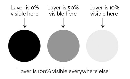
I will create textures mainly using Photoshop. I will create hand-painted materials, which are used in games with limited memory space or heavily game play related or animated. Ambient Occlusion maps take up too much space so aren't used with hand painted materials. Instead the light is painted into the albedo map. It is important I utilize the mask and adjustment layer options within this program, so it is easy to adjust my work at any point throughout the process. Layer masks use different values of grey to assign levels of transparency to areas of a layer or group of layers.
http://designshack.net/articles/graphics/a-complete-beginners-guide-to-masking-in-photoshop/
Adjustment layers uses colour and tonal adjustment, rather than grey like layer masks. It works like a filter, and the adjustments are applied to the image, but stored into a new layer.
For my next task I have textured a basic barrel. Using this template below, I hand painted the textures in Photoshop, saving them as PNG files and attaching them to my model in Maya. The model was already mapped, and I then exported the map into Photoshop. I found getting to grips with Layer masks hard to start with but now understand how to apply them and see the benefits. I used them to separate the metal and wood, ensuring that not textures from one went onto the other.


I added basic colours and then with more layers added darker and lighter areas, and with different brushes to get different effect for the grain.

I then added more detail and depth to the metal rims and darkened the cork. After group crit on this task, we agreed that the texture needs more highlights. I also should have done the grain running one way on the top of the barrel, not following the the lines on the UV map within the surface.
After a group critique session on our work so far, I got pointers on my barrel and how I could improve on it. The texture needs to be lighter, as the game engine would add the shadows to the item. It is too dark, so in future projects i shall try and get the colours as true to what they would be with no light source.


As a quick and basic project, I decided to create an asset from the Crash Bandicoot games. Mapping out the cube was quick and then transferring the map to Photoshop reinforced the process for me. I used the game image as reference, and quickly painted on the sides.

I applied the texture and this was the resulting outcome. I used only a few layers so it lacks depth and realism. The lines around the box also do not line up with each. Next time I will pay more attention to the seams when painting and ensure they line up perfectly.


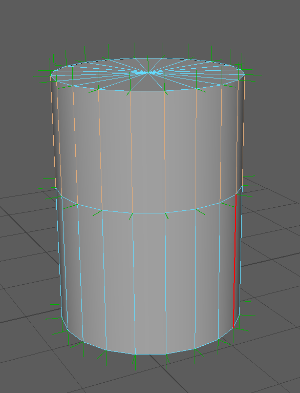
To firm my understanding of UV mapping, I created a basic cylinder with one extrusion and mapped it. I can see using the checkered pattern that there is no distortion. There is a lot of wasted space in the UV editor though, which would be filled with other maps for other models to utilize the space (such as coins or another small item.
Subdivision Modelling
There are two types of subdivision, which are interpolation and approximation. Interpolation will match the original position of the model and divide between the points (subdivision 'grid' will show on model but not alter any of the points). Approximation however will adjust the points of the model in all axis, which results in a smoother surface.
The first image shows interpolation subdivision. The subdivision has been increased by one from the left to the right.


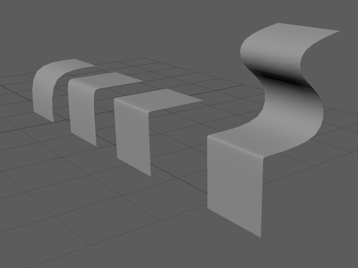
In our session where we applied our subdivision knowledge from the lecture, we used planes to experiment with the subdivisions and edge loops. Image below shows the objects not smoothed. The first 3 all look the same, however I have added edge loops to alter the smoothness.

With no edge loops, the left plane would smooth as shown. By adding edge loops to the other two, I could control the bend.

These are the same models, all in using the smooth preview option.


During our practical session we also played around with floaters ready for our next task. Floating geometry makes the illusion of details in the surface without having to cut into the mesh.

As the side display shows, these dips sit above the model and create the illusion when view from above.

Another material I will begin experimenting with is Phong, which is similar to Blinn. This material represents glossy or glassy surfaces that have a hard specular highlight.
Topology is also important in modeling and is often used when refering to character structure. Topology refers to the geometric surface characteristics of a 3D object. For an object (example, characters facial features) to animate correctly, the geometry needs to flow so it can deform correctly.

http://courses.cs.washington.edu/courses/cse458/13au/content/projects_458/project2/resources/face_topology_breakdown.jpg
A model must also be optimised, to ensure it is as efficient as possible so it performs its best during the next process. Any un-needed edges can be removed, reducing the amount of triangles and allocated in other areas if need be.
Our task on advance modelling is to create a vintage telephone, based off this image.

The base is the simplest to make. I have added edge loops to ensure the edges do not over smooth, as I want the edges to be reasonably sharp like the image.

Rather than extrude from the base model, I started with a new primitive and began modeling the metal stand to hold the phone. I duplicated as I went along, to ensure if anything went wrong I still had the base model. This means I could play about and experiment more easily without worrying about losing the base.

This is what they looked like smoothed


To get a nice smooth on the metal, I again added in edge loops around the areas I wanted to keep defined.
Using a cylinder, I began extruding and creating the telephone. The bottom item on the image below was my first attempt. I somehow extruded the segments separate and not as a whole face, resulting in this effect when it was smoothed. The inside also looked like the image underneath that. I had kept the original primitive so I could easily go back, duplicate and start again, ensuring this didn't happen. The top and middle models are the same, however the middle is the preview of smoothing.


Photoshop Tutorials
I have improved my knowledge of layers and channels in Photoshop after a workshop session on Photo-bashing. I understand how to isolate channels and create layer masks. Once I had placed the image on top of another, I could alter the layer type and effects over it. this helps blend the image into the background. This was my creation at the end of the session.

Material Instancing - UE4
In Unreal Engine 4, you can create what is refered to as a 'Parent' material, which is a master material and create multiple variations from that, which are called 'Children'. This is also called material instancing. It is a good method at getting a variety of materials yet saving memory space as the 'children' do not take up memory space.

http://docs.unrealengine.com/latest/images/Resources/Community/SciFiBunk_MaterialInstancing/image_16.jpg
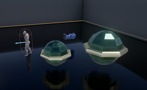
These plastics could all be instances from a parent material. When creating an instance of a material (child), the master material (parent) needs to have a series of parameters within the material which can be changed once instanced. These parameters could be colour, metalness and roughness.

When using UE4 for the first time, I experimented with the materials. I applied my bake which was uploaded to the textures folder, and then added more variables. I put parameters on the 'master material' so that I could instance this and see how much I could alter a child material.
This process is used as it allows us to conserve memory space as we are projecting the details from one mesh to another.
There are two methods of baking, Raycast and Cage. This image below is a simple diagram explaining what areas are rendered in the bake, when using the two methods. As you can see, cage is the preferred method for baking.

http://wiki.polycount.com/wiki/Texture_Baking#Cages
Raycasting casts invisible rays to capture other surfaces. The rays are positioned in the centre of each face on the object. Using the cage method however, a duplicate of the low poly model acts as the cage. It can capture corners and has no overlapping like ray-casting can.
Rules to follow when setting up baking cages:
- The cage needs to be identical to the low poly model created
- The cage needs to encompass the high poly model to get a correct projection on the low poly model
- When making the low poly model cage slightly larger than the high poly model, no extra geometry can be added.
Rays are cast from the faces of the low poly model, to the cage, which acts as a mirror and projects the high poly detail back onto the low poly mesh.

https://i.ytimg.com/vi/yeczjVAqznM/maxresdefault.jpg


Perspective
Linear Perspective's include one, two, three, four and even five point perspectives. These refer to the amount of vanishing points in that perspective.

https://danistdesgarcon.files.wordpress.com/2015/01/dscf0703.jpg

http://factore.ca/system/images/images/315/original/ingelmunster_perspective.jpg?1363111694

http://img09.deviantart.net/f00e/i/2012/308/e/9/3_point_perspective__by_masquedeglace-d5jzjmt.jpg
This 3 point perspective is also known as 'birds eye' view (as in the picture) or 'ant's eye' view when the third vanishing point is inverted.


Life Drawing


